
By Giulio Bocciolini, product marketing manager modular & configurable products EMEA, TDK-Lambda
Powering modern electronic systems requires careful selection of the right DC-DC conversion approach. One of the key design decisions that engineers face is whether to use an isolated or non-isolated converter. Each option brings distinct advantages and trade-offs in areas such as safety, efficiency, system complexity, and overall design flexibility. Understanding when and why isolation matters can significantly influence system architecture and performance. This article explores the factors engineers should consider when choosing between isolated and non-isolated DC-DC converters.
Modern electronics are increasingly complex. Product engineers are tasked with powering discrete loads with unique voltage and current characteristics, while facing pressure to improve efficiency and cost-effectiveness. Selecting a DC-DC power converter is a foundational design choice that determines whether isolation is required, with consequences that permeate the entire system design, impacting everything from safety and noise performance to size, weight, and cost.
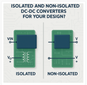
Figure 1: Isolated versus non-isolated DC-DC converter. Source: TDK-Lambda
The difference between isolated and non-isolated converters lies in the concept of galvanic isolation, which physically and electrically separates two parts of a circuit. An isolated DC-DC converter uses a transformer to transfer power between its input and output stages. There is no electrical conduction path between the two sides; instead, energy is transferred across an insulation barrier via a magnetic field. This creates two galvanically separate circuits, each with its own electrical reference. This barrier is the key to an isolated converter’s most valuable features: safety, electrical noise mitigation, and design flexibility.
A non-isolated DC-DC converter, by contrast, has a direct electrical path and a shared common electrical reference between its input and output. While this direct connection precludes the safety and noise benefits of isolation, it allows for a simpler, more compact, and often significantly more efficient design. The magnetic components that enable isolation are bulky, heavy, and costly. They also contribute to various energy-loss mechanisms in a power-conversion system.
This difference creates the central trade-off. The isolation barrier provides unparalleled safety and noise immunity, but comes at the cost of increased size, weight, complexity, and price. Conversely, a non-isolated converter offers superior performance in terms of efficiency, power density, and cost, but can only be used when the system architecture does not demand isolation.
Making the case for isolation
Isolated DC-DC converter selection is typically driven by requirements for safety, electrical noise immunity, or functional flexibility that a non-isolated converter simply cannot meet.
The most compelling reason to select an isolated converter is safety. In any system where the power converter is connected to a hazardous voltage, such as the AC mains or a high-voltage DC bus, an isolation barrier is generally a non-negotiable requirement to protect operators, users, and downstream electronics from potentially hazardous energy levels. If a fault occurs on the high-voltage primary side, the dangerous voltage cannot pass through to the accessible low-voltage secondary side.
In medical applications governed by IEC 60601-1, isolation requirements are especially stringent, with higher protection levels required where patient safety is involved. Meanwhile, in high-precision instrumentation, audio systems, and test and measurement equipment, electrical noise can corrupt sensitive signals and degrade performance. A common source of this noise is a ground loop, which occurs when interconnected pieces of equipment have different ground potentials, driving a noise current through the ground connection. An isolated converter is a powerful tool for breaking these ground loops. By powering a subsystem through an isolated converter, the DC ground connection between circuits is eliminated, silencing this noise source.
In complex systems such as industrial process controllers, different subsystems often operate with their own local ground references. Powering these from a common, non-isolated source can create unintended current paths. In systems with high transient loads, such as pumps and motors, temporary ground potential differences can also arise when current flows through ground impedances. Isolated converters allow each subsystem to maintain its own ground reference while receiving power from a central source.
Finally, the floating nature of an isolated converter’s output offers valuable design flexibility. A key application is generating a negative output voltage from a positive input. By connecting the positive output terminal of an isolated converter to the system’s primary ground, the negative output terminal will present a negative potential relative to that ground. This technique is commonly used to generate the -48 V supply required in many telecommunications systems, eliminating the need for a dedicated negative-output converter.

Figure 2: Telecommunications systems can benefit from the use of isolated DC-DC converters. Source: photostockatinat/stock.adobe.com
The non-isolated advantage
While isolation is critical in certain scenarios, it is often an unnecessary and costly addition. In some applications, a non-isolated converter is the superior choice, offering significant advantages in performance, size, weight, power, and cost (SWaP-C).
In many systems, the isolation decision is made at the architectural level. A popular approach is the distributed power architecture (DPA). In a DPA, a single, centralised AC-DC or high-power DC-DC converter provides the main safety isolation from the AC mains and generates a regulated intermediate DC bus voltage (e.g., 24 V or 48 V). Because this front-end converter has already provided the necessary safety isolation for the entire system, downstream converters usually do not need to be further isolated. This allows designers to use small, highly efficient, and low-cost non-isolated converters placed physically close to the components they are powering, leveraging the strengths of both converter types.
For applications where SWaP-C is the primary design driver, non-isolated converters are the clear choice. The main reason for their advantage is the elimination of components, such as the isolation transformer. Electrical spacings required by various safety standards increase with the maximum voltage present in the design. Often, circuits that can accept a non-isolated power topology operate at lower maximum voltages, resulting in smaller electrical spacings and a more compact design overall. This makes non-isolated converters the default solution for battery-powered mobile devices, commercial drones, autonomous mobile robots, and commercial aerospace applications where every gram and cubic centimetre counts.
Non-isolated converters also offer superior conversion efficiencies. By removing the transformer and its associated losses, efficiencies can reach 97 per cent or 98 per cent. High efficiency means less energy is converted to heat within the power system, simplifying thermal management and improving system reliability. These higher efficiencies also extend battery life in battery-powered applications.

Figure 3: A swollen smartphone battery highlights the importance of efficient power conversion to minimise heat in compact battery-powered devices. Source: cabuscaa/stock.adobe.com
From a design standpoint, non-isolated topologies offer a powerful toolkit. Common topologies in this class are the buck (step-down) and boost (step-up) converters. For ultimate flexibility, particularly in battery-powered systems where the input voltage varies widely, the four-switch buck-boost converter can operate as a buck or boost converter as needed, ensuring a stable output voltage across the entire battery discharge cycle.
Many non-isolated converters are designed with very wide input and adjustable output voltage ranges. This allows a single part number to be used across multiple products or to generate various output rails, simplifying the bill-of-materials (BOM), streamlining procurement, and accelerating development. In any system where the input source and the load already share a common ground, the added cost and complexity of an isolated converter provide little to no benefit, making a non-isolated topology the logical and most efficient choice.
A framework for decision-making
There is no single “best” solution between isolated and non-isolated DC-DC converters; the optimal choice depends entirely on the specific needs of the application. A logical framework for this decision is as follows:
- Is safety isolation mandated? If the system is powered from a hazardous voltage or must comply with standards such as IEC 60601-1, then galvanic isolation is required.
- If isolation is required, where is it best placed? For systems with multiple output rails, a DPA is often the superior choice. A single, centralized isolated converter can provide the primary safety barrier, allowing the use of smaller, more efficient non-isolated converters for the final voltage conversion steps.
- Are there functional needs for isolation? If the system does not require safety isolation, consider whether it is necessary to break a ground loop or generate an inverted voltage rail. If so, an isolated converter may be a better choice.
- If no to all of the above, default to non-isolated. If there are no mandatory safety or specific functional requirements for isolation, a non-isolated converter should be the default choice due to its advantages in efficiency, power density, size, weight, and cost.
Ultimately, power system design means correctly identifying and prioritising the most critical performance parameters for the end application. That makes the isolation decision a strategic rather than a purely technical choice.
www.emea.lambda.tdk.com/uk/products/dcdc-converters/
For more news please visit: News – CIE
